

Monday, September 28, 2015
Imagine the possibilities
When we installed our MultiCam CNC plasma cutter last week we weren't sure exactly what we would do with it. We just knew the things that are now possible in our shop will be very cool and unlimited in scope. It was the same with the MultiCam CNC router ten years ago. Today Peter designed the brackets for the gutters they will install on their house. The image was drawn by hand and then imported into EnRoute for vector tracing which only took a second. The back piece of the bracket was designed using the drawing tools. The first prototype was cut on the plasma cutter this morning. Cutting it from a sheet of 3/16" thick steel took less than a minute and welding it together only a minute more. The result is charming and will add a stunning detail to the house!
Dino comes to life!
The dinosaur bones were slipped over a bent steel pipe to form the backbone of the velociraptor. I spaced then out and took a look to see how it would work.

It needed a little tweaking and twisting to get things looking right. To give the skeleton more life I cut both ends of the pipe and added more bend before welding them back on at a slightly different angle. This brought the head and tail around in a more striking curve. I then tack welded things into place. I now have to do the final welds before we lift him onto a fallen tree which we will sculpt beneath him.

The mail box will be welded into his double handed grip. To get to this stage took less than an hour.


It needed a little tweaking and twisting to get things looking right. To give the skeleton more life I cut both ends of the pipe and added more bend before welding them back on at a slightly different angle. This brought the head and tail around in a more striking curve. I then tack welded things into place. I now have to do the final welds before we lift him onto a fallen tree which we will sculpt beneath him.
The mail box will be welded into his double handed grip. To get to this stage took less than an hour.
Tuesday, September 22, 2015
Pile of bones!
Once we got the new MultiCam plasma cutter set up and tested it was time to give it a spin. Russell asked me for a file and I was happy to oblige. It was time for Phoebe's mailbox to be cut at last! It was pure magic to watch it run through the file! It ran flawlessly - right out of the box!
We had quite the pile of pieces when the machine was done.


We had quite the pile of pieces when the machine was done.
Monday, September 21, 2015
Digging up some old bones
Yesterday, Russel Boudria, the head trainer from MultiCam in Texas arrived to set up our shiny new CNC plasma cutter and train us how to use it. He was eager to get started even though he had spent most of the day in transit. That's dedication! We worked a couple of hours levelling the table, sorting out wires, hoses and cables, and testing things out. We got to the point where we could move the gantry and test fire the machine. Tomorrow we'll begin some serious cutting. As I thought about what the first cut pieces might be I knew we would want to set a fairly high bar as the starting point. From here we will get even more creative. I knew just the test piece. Phoebe mentioned that she needs a mailbox for their new house. Ordinary just wouldn''t do. She also happens to love dinosaurs. So I thought a life-size velociraptor skeleton holding a custom built mailbox might be about right. Phoebe agreed. I designed the cutting file after Russel left. This is going to be FUN!

Tuesday, September 15, 2015
Complex robot arm - part four
Slicing reliefs in EnrRoute is actually pretty simple. Open the create slices menu. Then select the relief you wish to slice. It immediately tells you how tall your piece is - in this case it was 2.48"
 I selected the create ALL SLICES and changed the thickness to 2" It tells me that we now have two slices. I am happy with the result so I hit the green checkmark.

I immediately see a thicker blue outline and a second lighter outline of the slice. When you use the slice function it creates new reliefs but does not modify the original relief.

O I selected the reliefs, one by one and arranged them side by side. You can see the flat section we sliced off. The bottom arm is the original and is not modified. Since we don't need it anymore I moved it off to the side.

I then created a second copy of the sliced robot arm relief. I selected this duplicated relief and used the mirror tool to flip it. This reverse relief will be led to the back of the first to create a double sided model of the robot arm.

After dropping all of the reliefs to the bottom of the plate the piece is now ready to tool path and then route.

I immediately see a thicker blue outline and a second lighter outline of the slice. When you use the slice function it creates new reliefs but does not modify the original relief.
O I selected the reliefs, one by one and arranged them side by side. You can see the flat section we sliced off. The bottom arm is the original and is not modified. Since we don't need it anymore I moved it off to the side.
I then created a second copy of the sliced robot arm relief. I selected this duplicated relief and used the mirror tool to flip it. This reverse relief will be led to the back of the first to create a double sided model of the robot arm.
After dropping all of the reliefs to the bottom of the plate the piece is now ready to tool path and then route.
Complex robot arm - part three
The arm relief was merged highest with the zero height relief by using the merge highest command.

I then opened the extract slice function in EnRoute. The dialogue box immediately informs me of the thickness of the piece I have created... in this case 2.39". But at this point I only wanted to slice the bottom off effectively cutting my piece off of the zero height relief.


With the robot arm complete (for now ) it was time to urn my attention to the decorative base plate. I first used the offset drawing tool to create a border around the plaque and also Jeff's name.

The border (base relief) was built as a flat relief.

I then used the dome tool to lift the centre portion.


I used a texture batman called 'wiggly worms' to add the texture using the lettering outline as a mask so no texture went there.

I then used the lettering outline vectors to modify the base relief and raise this area above the texture.


I then used the lettering vectors and the prismatic tool to create the raised lettering. I used the constant height function to create a nicer bevel on the letters.

I then created the pedestal be for the robot arm by creating a new relief as a flat shape. In the front view we can see that is is too short. Fixing this is a simple matter of using the up arrows (in the front view) to nudge it up until I was happy.


The rivets were then built on top of this shape using the dome tool.


This pedestal relief was modified one last time by adding to the top of it to create the mounting point for the robot arm.

I then merged (highest) these two reliefs.

Checking in the front view I liked how everything worked.

I then selected both reliefs and brought them down to the bottom of the box. I adjusted the size of the pieces until they fit into a 2" thick plate with the exception base pedestal of the robot arm. We will next do a lice maneuver to be able to cut it out of a 2" thick piece of Precision Board. That will be saved for the next post.


Complex robot arm - part two
Now it is time to move on to the brush and pedestal of the robot arm. We use the create mesh/revolve tool for this operation. Open the dialogue box and simply follow the steps to create the mesh. I entered 100 for the values in the stacks and slices - this creates the resolution (number of facets) of the mesh.

As always it is important to do a render (in multiple views) to make sure that what happened was what you wanted.

The brush was created in the same manner.

Again I checked the render.

I then rotated the brush strictly by eye.

I then positioned the finished assembled over the base plate (not yet a relief) to make sure the brush and robot arm fit properly so the brush was painting the letters. I was happy with the result.

The next step was to make the meshes into reliefs as the router can't deal with meshes. To do this I made a flat (zero height) relief.

I then selected this new flat relief and the meshes to light up the combine meshes button. Make sure you select the merge highest function. One click and it was done. In the render view the mech(red) and modified relief appear as mottled. The mesh (red in the render but green when selected without render) can now be eliminated.

The robot arm should also be merged (highest) with this new relief.

Complex robot arm - part one
One of the projects I'll be sharing at the workshop is a fancy name plaque I did a couple of years ago for Jeff Hartman, one of the authors of EnRoute software. Their company is called Artistic Automation and so this seemed like a fitting idea. The projects used a bunch of the wonderful features of EnRoute Pro.


The vectors were all created using the draw tools in EnRoute. At this point I was not at all worried about scale, instead only thinking about how all of the elements related to one another.

Then I used the offset tool to begin adding areas that would be modified.

I also positioned the pill shaped pieces that would connect the elements.

Then it was time to start in on the reliefs beginning with the straight potion of the arms. These were made 0.75" thick.

The sunken portions of the arms were then created by modifying the first reliefs by sinking the centres 0.25".


The pill shaped connectors were built as separate reliefs.
Ditto for the travel limiters on the top of the robot arm.

The hydraulic cylinder brackets also were created in the same manner.

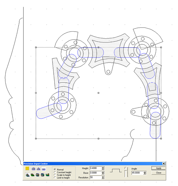
Next up was the robot arm hubs. I used the dome tool to create separate reliefs. The base (straight up portion) was set at 0.75" and the angle of the done set at 18 degrees.

Then the these reliefs were modified again by adding the outer ring of the centre.


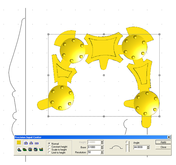
Lastly the centre point of the hub was raised using the dome tool once more.

I then selected all of the reliefs and used the combine tool to make the whole assembly once piece.

Subscribe to:
Posts (Atom)