WELCOME!


It is hard to believe that it was almost ten years ago I witnessed a CNC router in action for the very first time. I was fascinated with what I saw and simply had to have one! Although I had been in the creative end of the three dimensional sign business for most of my life I didn't really know what I would do with one - but I just knew it could do fantastic stuff.

Through extensive research and LOTS of hands-on practice I quickly found out that my MultiCam router was capable of just about anything imaginable.This journal will chronicle that journey to date and continue each week with two or three entries as I continue to explore just what is possible with this wonderful tool... -dan

Friday, February 26, 2016

Dustin

Dustin's name plaque was the next to be done. I used a method and tools that I don't often use in EnRoute. The vectors were designed (as usual) in EnRoute.


To create a chamfered edge I used the bevel tool and the 'limit to height' command. By defining the base (0.35") and the height of the finished relief (0.75") as well of the angle of the bevel (45 degrees)I had full control of the results. There are other ways of accomplishing this task in EnRoute but this is my favourite with a straight bevel (as opposed to a rounded one)


I then modified the base relief by raining the centre portion by 0.1"

The texture was the next addition using the same vector as a mask.


I then created a separate relief using the lettering border vector. It was a flat relief. I guessed at the height I required but this is not critical because after I created the relief I checked the front view and nudged it up one notch to create the look I was going for.


Here's the front view with the lettering outline selected.


I the]]hen merged highest to combine the two reliefs.


The last step was to create the lettering by again modifying the base relief using the lettering vectors. I used the dome tool but used the constant height option and defined the height of the dome as 0.07" The base (or vertical potion of the lettering was 0.15".


The name plaque was then ready to tool path and send off to the MultiCam. Askwith all of the name plaques they are being cut from 1.5" 30 lb Precision Board. I used a rough pass (50% overlap) with a 3/8" ball nose bit and a final pass (80% overlap) using a 1/8" ball nose bit. The piece was then cut out using a 3/8" cutter.


Viking arsenal!

Work has begun in earnest on the first of the features for the Viking project.


The crew has created quite the arsenal of Viking style weapons! Using EnRoute to create the files and the MultiCam Plasma cutter saved countless hours in creating these pieces. The same is true for the ships yet to come!


We used the plasma cutter to cut the bases for the features from half inch thick plate steel. The structural frames were then welded off of this base. The reason for the thick steel base is to minimize the chance of any possible damage to the sculpted concrete as it travels to Dubai and then is handles and installed by crews out of our control. The frames were created in bolt together sections to allow them to easily fit into the galvanizing vats. Once galvanized we will bolt them together and then do our usual sculpted concrete work. Assembled the pieces are designed to fit into shipping containers with a maximum height of 88"


The last shot is the pieces at the galvanizers when I dropped them off yesterday.

Saturday, February 20, 2016

Lorna's name plaque

It's that time once more. With the Sculpting Magic Workshops now just over seven weeks away it is time to begin preparations. That means it's time to do the name plaques which we present to all attendees. That's more than thirty different pieces to create. This time to make the plaques I decided to test a bunch of the new bitmaps I'm working as make them. 

The first piece will be a flag. The vectors were created in EnRoute. The lettering and rectangle vectors were created square and level and then I used the patch distort tool to create a waving flag.


I then created a flat relief.


I then imported one of the new bitmaps and applied it using a setting of 0.5". The result was a flag that waved vertically in a cool way.


The lettering outline was then raised.


Then it was time for the final step which was to use the bevel tool to 


The front and side views show how much the panel curves on the surface.


Friday, February 19, 2016

Glad you axed

With the plans, models and engineered drawings now behind us it is time at last to begin actual construction. The first bit to get the green light was the dock barrels, boxes and weapons. We decided for maximum reality we would build the axe heads and sword blades in steel. The vector files were created in EnRoute. For a little extra bling Peter whipped up a fancy little dragon which would be incorporated as an etching in the side of one of the axes. The MultiCam CNC plasma cut the parts in a few minutes and then the fun of assembly began. A square patch of metal was welded behind the dragon cutout and then the two faces of the axe were welded to some two inch stock. They were bent together at the blade and welded up. We then cut some steel wedge shaped flat stock to create the top and bottom and back of the axe. A little grinding smoothed everything out nicely. As a final step we welded on some pipe stock for the armature for the handle. We'll send it out for galvanizing before we sculpt the 'wooden' handle.


Ready... aim...

The Viking ship project has now grown to include a thirty foot and six foot wide targets (for water guns and the like) as well as some crates, barrels and weapon features for the dock. We first had to go through an extensive design process which involved models, concept drawings and many pages of engineered plans.


Wednesday, February 17, 2016

Branding

We have now produced five videos and we find they have really boosted our marketing efforts. These videos represent a large investment but have proven their worth already.

This month we had the opportunity to add another to the series. We wanted to talk about ( and more importantly show) how we can make place of business stand out from the crowd. The video features MultiCam's Western Canadian technical centre. Of course we turned to the talented fellows at Inmist Media House for their filming and editing expertise - and we think they knocked it out of the park again!

Friday, February 12, 2016

Massive plans

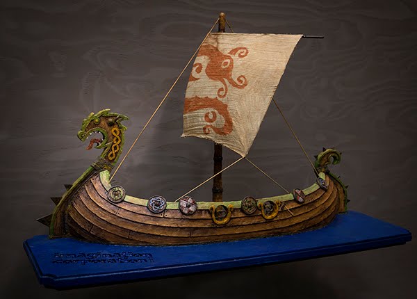
Our current big project is the design and fabrication of a pair of forty foot long Viking ships. We started with a scale model built at one inch to the foot. The model proved handy in our talks with the client, building confidence in our abilities to handle the project. The model also proved to be a great reference as we discussed how everything would go together.


Then we sat down at our design desk and started work on the plans. Being much more familiar with EnRoute than an architectural program we decided to use it to design the structural framework. The detailed plans also included all of the plasma cut steel (which is considerable) so the files will  be all ready be set to send off the router when we start. The plans were done in layers to help keep everything separate and in order. Peter and I spent two days so far creating the files. We still have a few details to build plus all of the sections, dimensions and notes. They say learning is best done by doing and it is very true. I've certainly learned a a great deal about how to use EnRoute in the last few days!


Thursday, February 4, 2016

New bitmap magic

Our TEXTURE MAGIC COLLECTION of bitmaps works really well, allowing us to achieve a whole lot of fancy and creative textures in a hurry. But many have asked me to work up more woodgrains for the next collection which will be released soon. I'm all ears. But I also wanted to take things a whole lot further to make the textures do much, much more. It is exciting to watch the new collection come together.

There will be lots of new woodgrains to choose from. But they will also be paired with some secondary bitmaps which will make the woodgrains much more believable. Special effects will also be possible with a third set of bitmaps in the collection to allow the wood to look twisted, warped or bent. Imagine what will be possible!

I tested the first set of bitmaps today by creating a name plaque for a new friend.

The thing to remember about bitmaps is that they work by reading the values. Black does nothing. While raises by the value you enter. Greys do something in between.

The bitmaps I used on this file are below. The top one was used to warp the board. The middle bitmap were used to enhance and add the character of the woodgrain on the bottom.


To start creating the file I first opened the bitmap files. The thing to remember in using multiple bitmaps that must be matched is that they need to be resized at the same time to maintain their proportions. I used the bottom woodgrain bitmap as a reference as I drew out the board vectors. I wanted this board to look weathered and old. 

Because I would be warping the board I created a second rectangle which I would use to build a separate relief and warp the to match the board. The lettering would be built up from this surface and then merged with the warped board. This way the two surfaces would match. The rivet band relief which would go along the right edge was also built separately and warped with the same bitmap.


I used the distort tool to wiggle up the rectangle and rivets. This would make them instantly old when I created the relief.


With the vectors complete I started making the simple flat reliefs. I started with the board.


The relief which I would build the lettering on was next.


The rivet band was last.


I then positioned the twist fade over the reliefs and applied it to all three of the reliefs. The resulting twist was subtle but most visible in the 3D render.


Next up I used the prismatic tool to modify the rivet band relief and create the rivets


The woodgrain was then applied to the biggest relief.


The woodgrain looked good but was naturally flat.


The paired relief which created a much more weathered and textured look fixed the flatness in a hurry!


I then added some weathering to the rivet band using the splotches bitmap (from the original collection)


I checked the end view to see how much the rivet band was sticking above the weathered wood. The twist of the board is evident in this view.


I then modified the rectangle relief by raising the lettering outline. It protruded through the woodgrain.


Once I had checked it and nudged it (up or down) appropriately in the front view it was time to MERGE HIGHEST with the wood relief. I also combined the wood and rivet band reliefs.


The lettering was then created by modifying the base relief using the lettering vectors as a mask.

Using those same lettering vectors I added the splotches bitmap to the lettering surfaces.


The file was then ready for tool pathing and was sent off to the Multicam to be cut from 1.5" 30 lb Precision Board. Once it was cut I used an air powered die grinder to add texture to the edges of the board plus cut a hole to create a knot hole in the board. It only took about five minutes to get the board ready for the hand sculpting, paint and gold leaf. Stay tuned for those steps.